What Is Void Ratio in Soil and Why Should Contractors Care?
If you have spent any time in earthwork, grading, or site preparation, you have heard a geotechnical engineer or inspector throw around terms like "void ratio," "relative density," and "degree of saturation." These words can feel like they belong in a university classroom rather than a job site trailer. But void ratio in soil is not an abstract concept. It is a measurable, practical number that directly influences how your fill behaves under load, how much material you need to move, and whether your project passes compaction testing the first time.
In 2026, the earthwork and excavation sector remains one of the most cost-sensitive segments of the construction industry. According to the U.S. Census Bureau's construction spending data, spending on infrastructure and site work continues to climb, with earthmoving and grading representing a significant portion of total project budgets on commercial, residential, and civil projects. Getting soil properties right from the start is not optional. It is financial discipline.
This guide explains void ratio clearly, connects it to the decisions contractors make every day, and shows you how to use this knowledge to control costs, meet specifications, and deliver better projects.
The Simple Definition of Void Ratio
Void ratio, typically expressed as the letter e, is the ratio of the volume of voids (empty spaces) in a soil mass to the volume of solid particles. The formula is straightforward:
e = Vv / Vs
Where:
- Vv = Volume of voids (air and water combined)
- Vs = Volume of solid particles
Because void ratio is a ratio of two volumes rather than a percentage of total volume, it can exceed 1.0. That is a key distinction from porosity, which we will address shortly. A highly loose, fluffy soil might have a void ratio of 1.2 or even higher. A densely compacted granular fill might achieve a void ratio as low as 0.3 to 0.5.
To put it in physical terms: imagine a bucket of marbles. The marbles themselves are the solid particles. The air space between them is the void volume. If you could measure both volumes precisely, their ratio would give you the void ratio of that "soil."
In practice, geotechnical engineers calculate void ratio from basic lab measurements. Technicians determine the dry unit weight and specific gravity of soil solids (typically around 2.65 to 2.72 for most mineral soils), then apply a simple relationship to derive void ratio. The governing test standards in the U.S. are published by ASTM International, particularly ASTM D2216 for water content, ASTM D854 for specific gravity, and ASTM D7928 or D422 for particle-size analysis.
Knowing the void ratio of your native soil and your fill material before you start grading gives you a predictive tool. It tells you how much that soil will compress, how much water it can hold, and how it will behave under the weight of a structure or pavement.
Void Ratio vs. Porosity: Understanding the Difference
Contractors often encounter both terms, and the confusion between them is understandable. Both describe the "emptiness" of a soil, but they are calculated differently and used in different contexts.
Porosity (n) is the ratio of void volume to total volume:
n = Vv / Vt
Where Vt is the total volume of the soil sample (solids plus voids).
Because total volume always includes the voids themselves, porosity is always a number between 0 and 1, typically expressed as a percentage.
Void ratio (e) divides by the volume of solids only, so it can theoretically be any positive number, though values above 2.0 are rare in practice.
The two values are mathematically related:
n = e / (1 + e) and conversely e = n / (1 - n)
So a soil with a void ratio of 0.65 has a porosity of about 39.4%. A soil with a void ratio of 1.0 has a porosity of exactly 50%.
Why does the industry use void ratio more than porosity in geotechnical work?
The answer is mathematical convenience. When soil compresses or expands, the volume of solid particles stays essentially constant. Only the void volume changes. Because void ratio normalizes against the constant (solid volume), it is far easier to track changes in soil state during consolidation, compaction, and settlement analysis. Porosity, by contrast, changes its denominator as the soil compresses, making calculations more cumbersome.
For contractors, the practical takeaway is this: when your geotech report references void ratio, they are giving you a precise, engineering-grade measure of how densely packed your soil particles are. When a soil survey references porosity, you are getting a percentage-based snapshot that is useful for understanding drainage and water storage capacity.
| Property | Formula | Typical Range | Primary Use |
|---|---|---|---|
| Void Ratio (e) | Vv / Vs | 0.3 to 1.5+ | Compaction, settlement, consolidation |
| Porosity (n) | Vv / Vt | 25% to 70% | Drainage, permeability, water storage |
| Degree of Saturation (S) | Vw / Vv | 0 to 100% | Moisture condition assessment |
| Dry Unit Weight | Ws / Vt | 85 to 135 pcf | Compaction spec compliance |
How Void Ratio Connects to Soil Compaction
Here is where void ratio stops being a classroom concept and becomes money in your pocket or out of it.
Compaction is, at its core, the process of reducing void ratio. When you run a vibratory roller or a tamping foot compactor over a lift of fill, you are forcing soil particles closer together, collapsing air voids and expelling air from the pore spaces. The end result is a lower void ratio, a higher dry unit weight, and a stronger, more stable soil mass.
Most earthwork specifications require a minimum compaction level expressed as a percentage of maximum dry density. In the U.S., this is typically tested using ASTM D698 (Standard Proctor) or ASTM D1557 (Modified Proctor), depending on the application. A road subbase might require 98% of Modified Proctor maximum dry density. A residential structural fill might call for 90 to 95% of Standard Proctor.
Here is the critical link: every compaction specification corresponds to a target void ratio range, even if the spec never states it explicitly. When a project calls for 95% of Standard Proctor, the engineer has calculated a maximum allowable void ratio that the compacted fill must not exceed.
Real-world example: A sandy loam fill with a specific gravity of 2.68 and a Proctor maximum dry density of 118 pcf has a minimum void ratio at that density of approximately 0.42. If field compaction testing returns a dry unit weight of only 108 pcf, the void ratio is roughly 0.55. That gap of 0.13 void ratio units does not sound dramatic, but it translates directly to lower bearing capacity, greater settlement potential, and possible rejection by your inspector.
Failing a compaction test means re-compacting, re-testing, and absorbing the cost of additional equipment hours and inspector fees. On large site work projects, that can add up to tens of thousands of dollars quickly.
For contractors managing fill sourcing alongside compaction requirements, finding material with consistent gradation and manageable moisture content is essential. Platforms like DirtMatch help earthwork contractors connect with vetted fill dirt sources that match their project's material specifications, reducing the risk of importing poorly graded or over-wet soil that fights compaction from the start.
What Factors Control Void Ratio in the Field?
Understanding what drives void ratio up or down gives contractors practical leverage over their results. The five main factors are soil type, particle gradation, moisture content, compaction energy, and number of passes.
Soil Type and Particle Shape
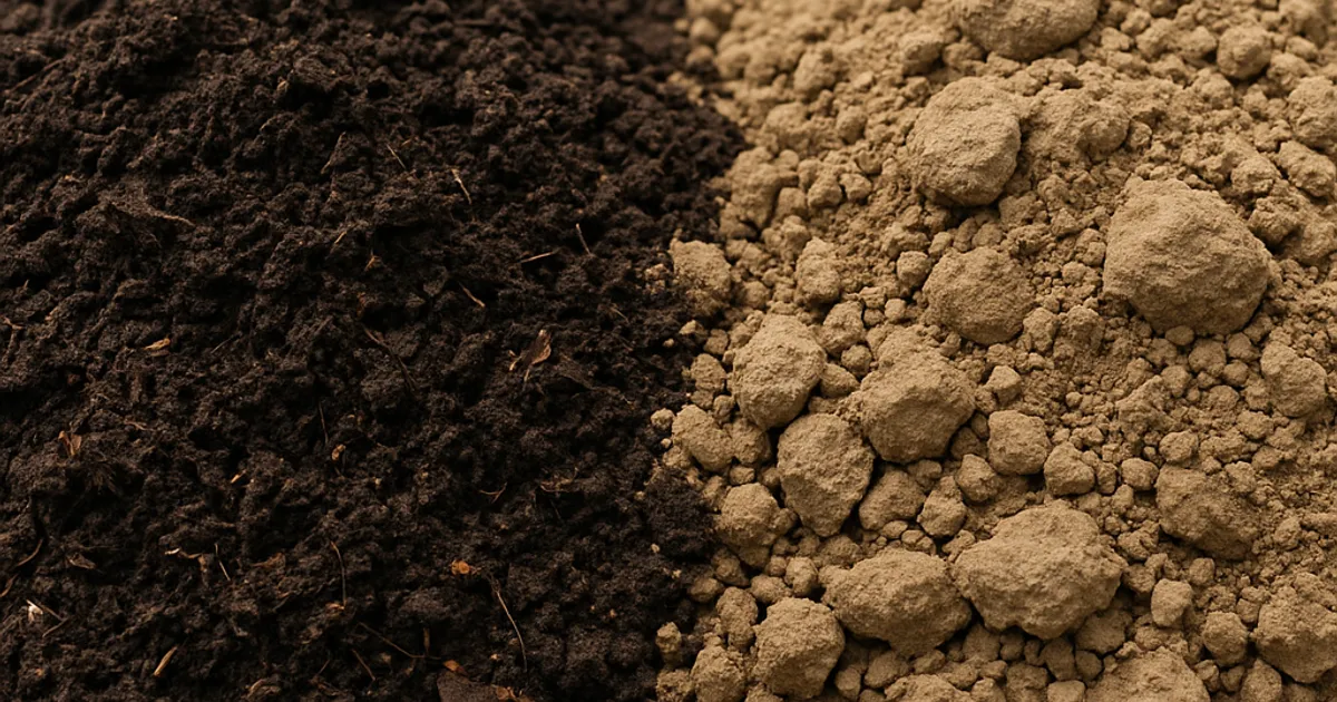
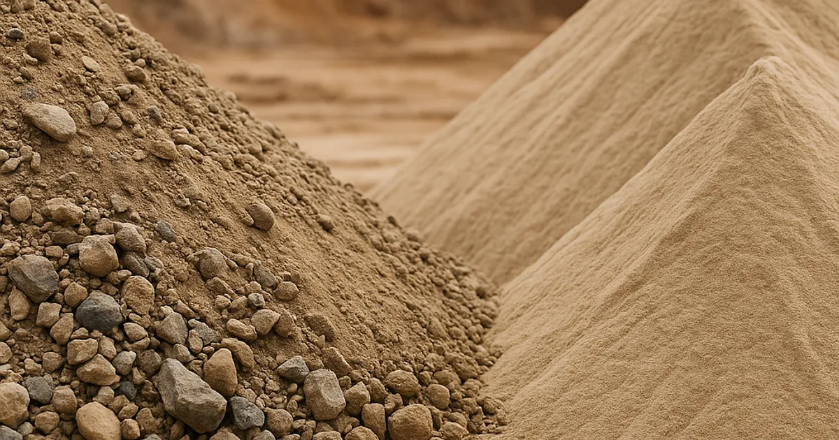
Angular, well-graded particles interlock more tightly than rounded, uniformly sized particles. A well-graded gravel (classified as GW under the Unified Soil Classification System) can achieve very low void ratios, often below 0.35 under proper compaction. A uniformly graded fine sand (classified as SP) has particles that cannot interlock as efficiently, resulting in higher minimum void ratios even with excellent compaction effort.
Highly plastic clays and organic soils present a different challenge. These soils can have natural void ratios exceeding 2.0 in their undisturbed state. Organic content holds water in the soil structure, maintaining high void volumes that resist compaction. This is why specifications for structural fills almost universally prohibit organic material and limit plasticity index.
Particle Gradation and the "Fill Factor"
Well-graded soils contain particles of many sizes, allowing smaller particles to fill the voids between larger ones. This nested packing produces much lower achievable void ratios. When evaluating potential fill sources, reviewing the grain size distribution curve from sieve analysis (ASTM D6913) tells you whether a material can realistically reach your target void ratio under the compaction equipment you have on site.
Moisture Content: The Lubrication Effect
Water in soil acts as a lubricant, allowing particles to slide into denser arrangements during compaction. Too little moisture and particles cannot move freely. Too much moisture and the voids fill with incompressible water, preventing further densification. The optimum moisture content, determined by Proctor testing, is the sweet spot where void ratio can be reduced most efficiently with a given compaction effort.
Seasonal moisture variation is a real challenge in regions with significant rainfall or freeze-thaw cycles. Contractors working on projects in high-rainfall areas like the Pacific Northwest or the Northeast need to monitor in-situ moisture closely and adjust compaction scheduling accordingly.
Compaction Equipment and Energy
Different compaction tools apply energy differently. Vibratory smooth drum rollers work best on granular soils, creating dynamic force that collapses voids effectively. Padfoot (sheepsfoot) rollers are ideal for cohesive clays, kneading particles into denser arrangements. Plate compactors are suited for confined areas and granular backfill around utilities. Selecting the wrong tool for the soil type means more passes, more fuel, more time, and potentially still not reaching the target void ratio.
Void Ratio and Settlement: The Long-Term Consequence
Compaction is not just about passing a test during construction. It is about controlling what happens to a structure five, ten, and twenty years down the road. The relationship between void ratio and settlement is one of the most important concepts in applied geotechnical engineering.
When a load is applied to a soil mass with excess void ratio, the voids gradually collapse over time as water is squeezed out in a process called consolidation. This is the primary cause of differential settlement, which is among the most destructive forces a building, pavement, or pipeline can experience.
The rate and magnitude of consolidation settlement are quantified using the compression index (Cc) and the coefficient of consolidation (Cv), both of which are derived from void ratio measurements at different stress levels during laboratory oedometer testing. These values feed directly into structural and geotechnical design, determining the thickness of surcharge fills, the need for wick drains or stone columns, and the required construction sequencing.
For contractors, the practical implication is this: poorly compacted fill with excess void ratio will settle after the project is complete, and the liability often falls on the contractor who placed it. In residential construction, post-construction settlement claims are among the most common causes of construction defect litigation.
Beyond structural loads, poor void ratio control affects pavement performance significantly. The Federal Highway Administration estimates that premature pavement failure due to inadequate subgrade compaction costs the U.S. billions of dollars annually in maintenance and rehabilitation. Contractors who understand and control void ratio from the start are directly contributing to infrastructure longevity.
Reading Geotechnical Reports: Void Ratio Data You Will Encounter
Most earthwork contractors receive a geotechnical investigation report before starting a project. Knowing how to extract and use void ratio information from that report is a competitive advantage.
Key Tables and Data to Look For
Boring logs typically include visual soil classification, blow counts from Standard Penetration Testing (SPT, ASTM D1586), and moisture content measurements. SPT blow counts correlate loosely but usefully with relative density for sands, which in turn correlates with void ratio.
Laboratory summary tables often include specific gravity, Atterberg limits, and Proctor test results. From the Proctor maximum dry density and the specific gravity, you can calculate the void ratio at Proctor maximum using:
e at Proctor max = (Gs x γw / γd_max) - 1
Where Gs is specific gravity, γw is the unit weight of water (62.4 pcf), and γd_max is the Proctor maximum dry unit weight in pcf.
This calculation gives you the theoretical minimum void ratio achievable with Standard or Modified Proctor effort, which anchors your field compaction target.
Consolidation test results report e-log p curves (void ratio plotted against log of effective stress). These show how the soil's void ratio decreases as overburden pressure increases and directly predict how much a compressible layer will settle under structural loads.
Recommendations sections of geotech reports typically specify allowable bearing capacity, required compaction levels, and sometimes explicitly reference maximum allowable void ratios for special materials like controlled low-strength material (CLSM) or engineered fill.
If your geotech report is silent on a specific condition you encounter in the field, reaching out to the project geotechnical engineer of record is always the right move before proceeding.
Find or Post Dirt, Rock & Aggregate
Join thousands of contractors using DirtMatch to buy, sell, and exchange earthwork materials.
Try DirtMatch FreeVoid Ratio Across Different Soil Types: A Practical Reference
Not all soils behave the same way, and understanding the typical void ratio ranges for different soil classifications helps contractors set realistic expectations and communicate more effectively with design teams.
| Soil Type | Natural Void Ratio Range | Typical Compacted Void Ratio | Compaction Challenge Level |
|---|---|---|---|
| Clean Gravel (GW) | 0.30 to 0.60 | 0.25 to 0.40 | Low |
| Well-Graded Sand (SW) | 0.45 to 0.75 | 0.35 to 0.55 | Low to Moderate |
| Poorly Graded Sand (SP) | 0.60 to 0.90 | 0.50 to 0.70 | Moderate |
| Silt (ML) | 0.55 to 1.10 | 0.50 to 0.75 | Moderate to High |
| Lean Clay (CL) | 0.60 to 1.20 | 0.55 to 0.80 | High |
| Fat Clay (CH) | 0.90 to 2.50 | 0.75 to 1.20 | Very High |
| Organic Soils (OL/OH) | 1.50 to 4.00+ | Not suitable for structural fill | Extremely High |
| Soft Marine Clay | 1.20 to 3.50+ | Not suitable without improvement | Extremely High |
This table reinforces a core principle for earthwork contractors: the quality of fill material you import has a direct bearing on how efficiently you can compact it and what void ratio you can realistically achieve. Selecting appropriate borrow material is not just a logistics decision. It is a geotechnical one.
Contractors sourcing fill for projects in competitive markets like dirt exchange in Denver or dirt exchange in Los Angeles know that finding clean, well-graded material quickly can determine whether a project stays on schedule. Having access to a marketplace that connects you with local material sources removes a major sourcing bottleneck.
Measuring Void Ratio in the Field: Testing Methods Contractors Should Know
Theoretical knowledge of void ratio matters only if you can measure and verify it during construction. Field quality control relies on several well-established methods, each with its own strengths and appropriate applications.
Nuclear Density Gauge
The nuclear density gauge (Troxler gauge or similar) is the most widely used field compaction testing tool in the U.S. It uses gamma radiation and neutron emission to simultaneously measure dry unit weight and moisture content of compacted fill. From those measurements, the field technician can calculate in-place void ratio and degree of saturation.
Nuclear gauges require certification and compliance with NRC regulations regarding radioactive materials handling. They are fast, providing results in about one minute, and are accurate for a wide range of soil types.
Sand Cone Method
The sand cone test (ASTM D1556) is a traditional, non-nuclear method for measuring in-place density. A calibrated volume of sand is poured into an excavated hole in the compacted fill, and the weight of the displaced soil is used to calculate dry unit weight. It is slower and more labor-intensive than the nuclear gauge but does not require radioactive material licensing and is often preferred for verification testing.
Drive Cylinder Method
The drive cylinder or drive sleeve method (ASTM D2937) is used for cohesive, fine-grained soils where a thin-walled cylinder can be driven into the soil and a sample extracted with a known volume. It is straightforward and requires minimal equipment.
Electrical Density Gauge (Non-Nuclear Alternatives)
In 2026, non-nuclear density gauges have gained significant traction on job sites where handling radioactive materials poses logistical or regulatory challenges. Devices using electromagnetic or impedance-based technology can approximate density and moisture without the NRC compliance burden, though their accuracy in highly variable soils requires careful calibration.
Intelligent Compaction Technology
Perhaps the most significant advancement in void ratio verification is intelligent compaction (IC), where GPS-equipped rollers with accelerometers measure the stiffness of compacted soil in real time across the entire compacted area, not just at test points. Manufacturers like Caterpillar and Komatsu now offer IC-equipped rollers that create continuous compaction maps, allowing quality control engineers to identify soft spots before they become post-construction problems.
Void Ratio and Fill Material Sourcing: The Contractor's Supply Chain Problem
Even a contractor who fully understands void ratio and compaction theory can be undermined by poor fill material. The source of your fill determines the grain size distribution, the natural moisture content, the plasticity characteristics, and ultimately the minimum achievable void ratio on your project.
Common fill sourcing problems that blow up compaction results include:
- Over-wet clay fill delivered during a rainy season that cannot be dried to optimum moisture content without significant delay
- Contaminated fill with wood debris, organic matter, or construction waste that inflates void ratio and resists compaction
- Uniformly graded fine sand from a nearby sand pit that has inherently higher minimum void ratios than a well-graded borrow source
- Expansive clay trucked in from a region with high montmorillonite content that swells and shrinks with moisture changes, defeating compaction in the long run
These problems are not just technical annoyances. They translate directly into schedule delays, material rejection, haul-back costs, and in some cases, contractual disputes over specification compliance.
This is exactly where DirtMatch adds real value for earthwork contractors. By connecting fill providers and fill receivers within the same region, DirtMatch makes it easier to evaluate material sources before committing to a haul, reducing the risk of receiving fill that cannot meet your project's void ratio and compaction requirements. Contractors who learn how DirtMatch works often find they can cut material sourcing time significantly while gaining more transparency about the material they are importing.
Regulatory and Specification Context for Void Ratio
Void ratio does not exist in a regulatory vacuum. Multiple standards and specifications govern when and how it must be measured, documented, and achieved.
ASTM Standards
The ASTM International suite of soil testing standards is the backbone of compaction quality control in the U.S. Key standards relevant to void ratio in earthwork include:
- ASTM D698: Standard Proctor compaction test (defines maximum dry density and optimum moisture content for lower-energy applications)
- ASTM D1557: Modified Proctor compaction test (higher energy for pavement subgrade and structural fills)
- ASTM D2216: Laboratory determination of water content
- ASTM D854: Specific gravity of soils (critical input for void ratio calculations)
- ASTM D1556: Sand cone in-place density
- ASTM D6938: Nuclear methods for density and moisture
- ASTM D2937: Drive cylinder method
AASHTO Standards
For highway and transportation projects, the AASHTO standards often run parallel or are directly referenced in state DOT specifications. AASHTO T 99 and T 180 correspond to Standard and Modified Proctor, respectively. State DOTs may specify either ASTM or AASHTO methods depending on project type and funding source.
OSHA Soil Classification
While OSHA's excavation standards under 29 CFR 1926 Subpart P focus primarily on worker safety in trenches and excavations rather than void ratio directly, soil classification under OSHA's Type A, B, and C system is related. Type A soils (the most stable) correspond to cohesive soils with low void ratios and high unconfined compressive strength, while Type C soils (requiring the most protective systems) include granular soils with high void ratios and cohesionless, running characteristics.
Common Mistakes Contractors Make Related to Void Ratio
Knowing the theory is one thing. Avoiding the field mistakes that come from ignoring it is another. Here are the most common errors that experienced earthwork contractors have learned the hard way.
Lifting Too Thick
Every compaction specification includes a maximum loose lift thickness, typically 6 to 12 inches depending on soil type and equipment. Compacting lifts that are too thick means the compaction energy does not penetrate to the bottom of the lift, leaving high void ratios in the lower zone even as the surface tests acceptably. This creates a sandwich of well-compacted soil over poorly compacted soil, a recipe for post-construction settlement.
Testing Only at Convenient Spots
Inspectors who test only at easy-access locations can miss soft spots in corners, along walls, and under utility pipes. Intelligent compaction technology helps address this by providing areal coverage rather than point measurements, but on conventionally tested projects, QC plans should require systematic, grid-based testing that covers all areas of the fill, not just the center of the pad.
Ignoring Material Change During a Haul
Fill material from a single borrow source can vary significantly across the excavation area. A contractor who runs Proctor testing on one load and assumes it applies to the next fifty loads is taking a significant risk. When material gradation or plasticity changes, the optimum moisture content and maximum dry density change, and your target void ratio shifts accordingly. Periodic retesting of borrow material during a long haul operation is not over-engineering. It is basic QC.
Compacting Saturated Soil
Pressing ahead with compaction when fill is saturated does nothing productive. Air voids have already been replaced by water, and additional compaction energy causes shear distortion (pumping) rather than densification. The result is a "compacted" lift that actually has higher void ratio instability than one that was placed at optimum moisture. Waiting for soil to dry to within a few percentage points of optimum moisture content before compacting is almost always worth the delay.
Practical Takeaways for Earthwork Contractors in 2026
Void ratio is not just a number geotechnical engineers care about. It is a fundamental measure of how well your earthwork is performing, and it has direct financial consequences on every project you run. Here is a condensed action list:
Read your geotech report before you bid. Identify the compaction specifications, the Proctor test results, and any explicit void ratio requirements. Budget accordingly for the compaction effort required.
Evaluate fill sources with the same rigor as structural materials. Request grain size analyses and Proctor test data from borrow pit operators. Material that looks acceptable visually can have gradation characteristics that make target void ratio nearly impossible to achieve.
Match compaction equipment to soil type. Vibratory smooth drum for granular, padfoot for cohesive. Do not assume one machine handles everything optimally.
Respect lift thickness limits. Exceeding maximum loose lift thickness is one of the most common causes of failing density tests at depth.
Monitor moisture continuously. Compacting soil that is too wet or too dry wastes effort and produces poor void ratio results regardless of equipment quality or number of passes.
Invest in IC technology where the project justifies it. Continuous compaction mapping eliminates the guesswork and provides defensible documentation if post-construction settlement claims arise.
Use regional material marketplaces to find quality fill faster. Contractors working across growing metro areas like dirt exchange in San Francisco or dirt exchange in Boston can reduce hauling distances and material sourcing uncertainty by connecting with vetted local sources through platforms designed for the earthwork industry.
For contractors ready to take their material sourcing and project execution to the next level, get started with DirtMatch and see how the platform connects fill providers and receivers across the regions where your projects are running.
The Bottom Line: Void Ratio Is a Profit Lever
Every percentage point of unnecessary void ratio in your compacted fill represents potential settlement, potential rejection, and potential liability. The contractors who consistently win repeat work from developers, municipalities, and general contractors are the ones who deliver compaction results the first time, every time, and do so with materials that make the job easier from the start.
Void ratio in soil is the invisible metric that separates good earthwork from great earthwork. It is testable, controllable, and predictable when you understand the factors that govern it. Use it as a tool, not a mystery, and your project outcomes will reflect the difference.